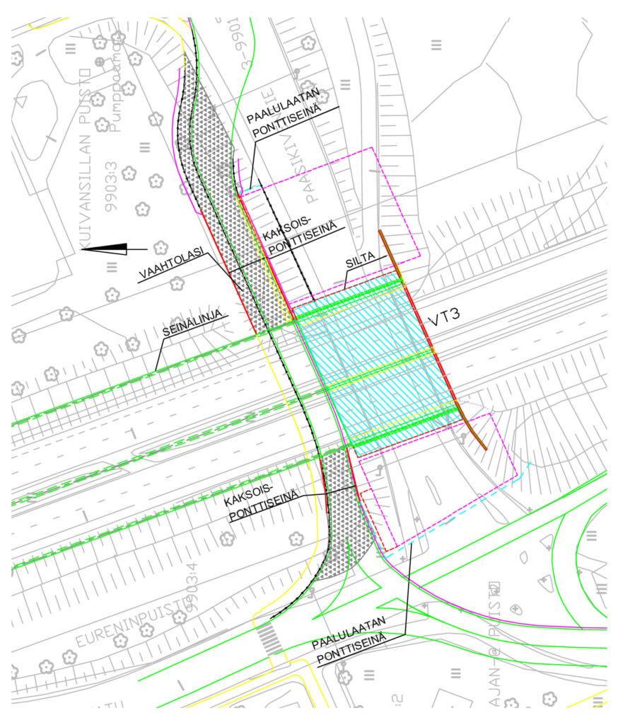
The project was part of a larger redevelopment of central Hämeenlinna. When Finnish national road 3 was covered over, an access ramp and slip road were also constructed. Once the cover was complete, construction began on a shopping centre, part of which was built on the cover over the road. The worksite was in a very central location, and the traffic volumes are substantial, both on the Finnish national road and in the city’s street network.
The project involved two old bridges, which were demolished and replaced by new bridges. During demolition and construction, traffic was routed over the sections of the cover that were already built adjacent to the bridges. The cover is located high about the surrounding ground level. At most, the ascent onto the cover was approximately eight metres, so four ramps were built with a total length of approximately 350 metres.
It was not possible to build the ramps in the form of gravel embankments and gravel infill between sheet piles due to the stability problems and the lateral loads acting on the piles. Foam glass aggregate was used to build the ramps in the form of lightened embankments.
Ground conditions
In the tunnel, there was an old layer, 1–3 metres thick, of motorway infill, mainly containing sand and gravel. The thickest layer of infill was around the Turuntie and Paasikiventie bridges.
The current road structures have natural foundation beds, and any peat has presumably been removed from beneath the structures. Outside the road area, there are areas with 1–2.5 metres of peat, partly beneath the current infills.
Underneath the layer of infill and peat is a layer of silt and lean clay 10–17 metres thick. The boring resistance of the cohesion soil increases substantially at a depth of about 10 metres below the surface. The soil samples taken from the silt and clay layers contained 17–72% water. The unreduced, undrained shear strength, determined using vane apparatus on the softest uppermost layer of cohesion soil, is 12–32 kN/m2.
The top surface of the moraine is located an average of 13–15 metres below the surface. The moraine layer has a thickness of 0–5 metres. Based on pressure ram sounding, the moraine is very loose and, in places, rocky. The rock surface, as determined using motorised dynamic sounding, is at a depth of 13–21 metres.
Solutions
Normal gravel infill between sheet piles was not possible, as it would have caused stability problems and lateral loads on the piles. It would also have increased the amount of material and requirements for the sheet piles and anchors. Using piled structures as the foundations for the transport routes used during construction would have been a very expensive solution.
For these reasons, foam glass aggregate was chosen, not least for its technical properties and the ease of construction and reuse.
Thanks to the low density and large angle of repose offered by foam glass aggregate, it was possible to reduce the load acting on the subsoil and the sheet pile walls, while limiting lateral loads on the piles of other structures. Due to the large angle of repose offered by foam glass aggregate, it was possible to construct high embankments without any intermediate layers or supporting structures.
A total of approximately 10,000 m3 of foam glass aggregate was delivered to the worksite to fill four embankments.
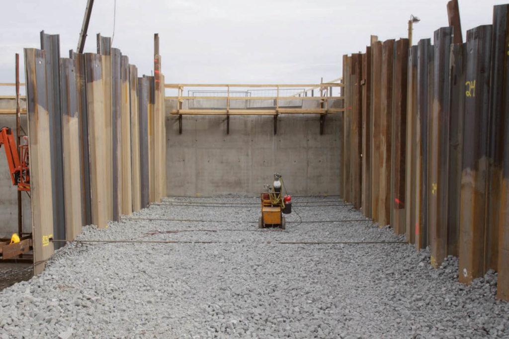
The lack of working space around the demolished abutments called for a narrower structure, which was realised by compacting the foam glass between two sheet pile walls.
Dimensions and structure of the access ramp
A characteristic value of 40° was used for the angle of repose of the foam glass aggregate. The calculations used a bulk density of 4 kN/m3 for the foam glass aggregate. The thickness of the layer of foam glass aggregate between the sheet pile walls was 3.5–7.3 metres, with a maximum value of 3.5 metres within the embankment structures. The structural layers of the road on top of the foam glass embankment consisted of approximately 650 mm of aggregate and 50 mm of asphalt.
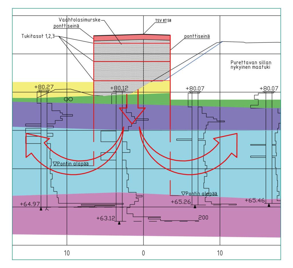
An inclined embankment was used in the area with sufficient stability to resist the collapse of the ground and less restricted working space. The inclined embankment was built from foam glass aggregate without requiring separate supporting embankments. The embankment was up to 85 kN/m2 lighter than an equivalent gravel structure, and the soil pressure was reduced by approximately 60%. The solution was designed and modelled using several geotechnical calculation applications, including Plaxis and Geocalc.
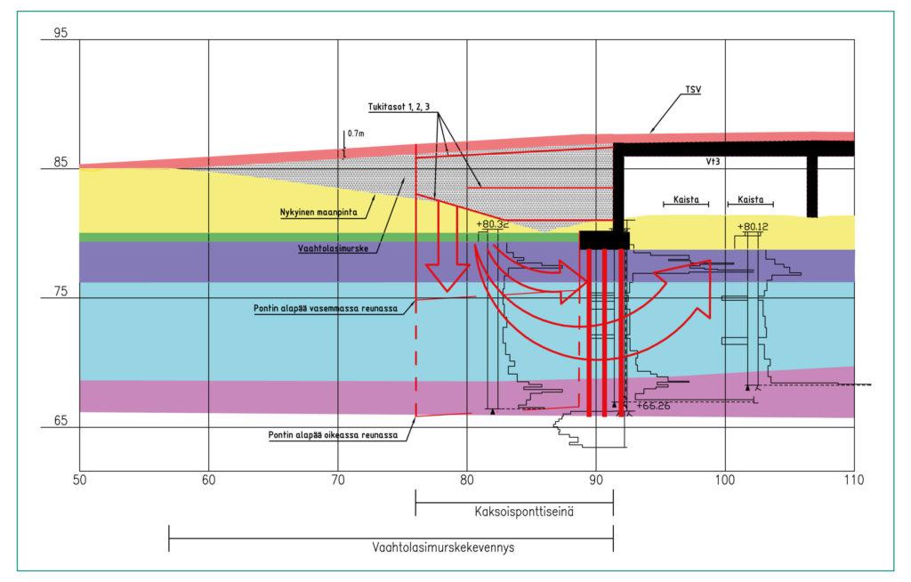
The sheet pile was of a normal type, and the sheet pile walls were extended by welding. The sheet piles were anchored to each other using 32 mm corrugated bars at two or three support levels, depending on the height of the embankment. The installation depths of the sheet piles depended on the local stability requirement. Near the excavations for the bridge abutments, the sheet piles were embedded 5–10 metres deeper than on the other side, where the natural ground level was higher. The maximum sheet pile length was approximately 20 metres.
Challenges
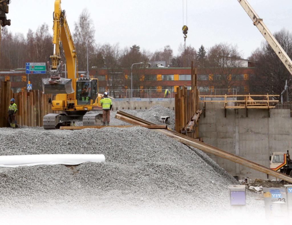
The demolition and excavation of the bridge abutments and the driving of new piles and construction of pile slabs right next to the sheet pile wall of the foam glass structure required the use of long, extended sheet pile walls to ensure local stability. Further challenges were the tight schedule and worksite logistics, exacerbated by the heavy traffic in the area.
Construction
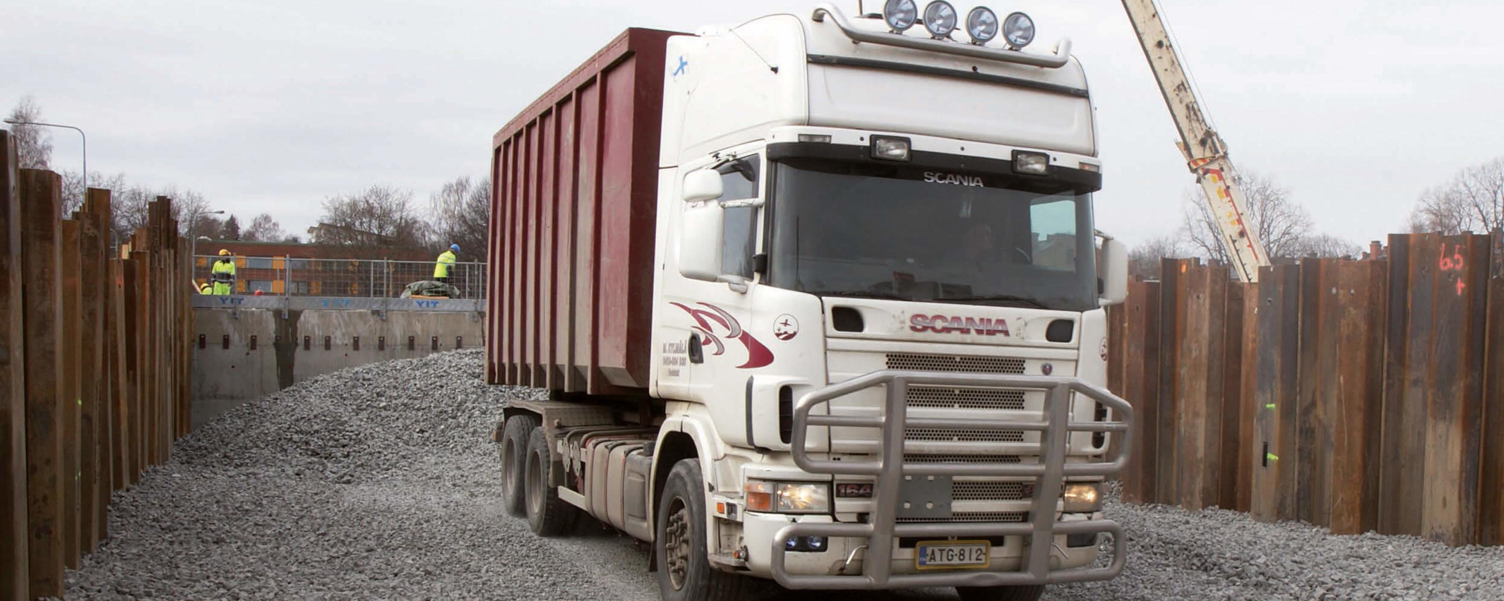
The foam glass aggregate embankment was built in 0.7-metre layers and compacted using a tracked compactor, after which it was possible to drive lorries over the compacted layer. The layers were arranged in such a way that the draw bars were installed in the top surface of the compacted layer. A vibrating compactor was used at the edges and corners to ensure that the material was compacted. The compaction was successful, and the tyres of the lorries driving on the new layer did not cause the aggregate to subside.
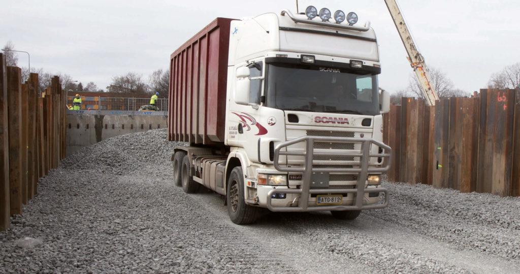
The material was delivered on lorries with traction units carrying 40 m3 pallets and trailers containing two more 40 m3 pallets. This solution reduced the amount of lorry traffic to one-quarter of the amount required for a conventional gravel delivery by lorry. The embankment was built at a rate of more than 1,000 m3 per day.
Foam glass aggregate made it possible to build an inclined embankment several metres in height without edge supports or intermediate layers.
 Contact us